- Overview
- Configuration
- Technical
-
RFC 1305
- 1. Introduction
- 1.1 Related Technology
- 2. System Architecture
- 2.1 Implementation Model
- 2.2 Network Configurations
- 3. Network Time Protocol
- 3.1 Data Formats
- 3.2 State Variables and Parameters
- 3.3 Modes of Operation
- 3.4 Event Processing
- 3.4.1 Notation Conventions
- 3.4.2 Transmit Procedure
- 3.4.3 Receive Procedure
- 3.4.4 Packet Procedure
- 3.4.5 Clock-Update Procedure
- 3.4.6 Primary-Clock Procedure
- 3.4.7 Initialization Procedures
- 3.4.7.1 Initialization Procedure
- 3.4.7.2 Initialization-Instantiation Procedure
- 3.4.7.3 Receive-Instantiation Procedure
- 3.4.7.4 Primary Clock-Instantiation Procedure
- 3.4.8 Clear Procedure
- 3.4.9 Poll-Update Procedure
- 3.5 Synchronization Distance Procedure
- 3.6 Access Control Issues
- 4. Filtering and Selection Algorithms
- 4.1 Clock-Filter Procedure
- 4.2 Clock-Selection Procedure
- 4.2.1 Intersection Algorithm
- 4.2.2. Clustering Algorithm
- 5. Local Clocks
- 5.1 Fuzzball Implementation
- 5.2 Gradual Phase Adjustments
- 5.3 Step Phase Adjustments
- 5.4 Implementation Issues
- 6. Acknowledgments
- 7. References
- Appendix A
- Appendix B
- Appendix C
- Appendix D
- Appendix E
- Appendix F
- Appendix G
- Appendix H
- Appendix I
- About
- Time Tools
| Previous Top Next |
Windows Time Client
Appendix HAnalysis of Errors and Correctness Principles
Introduction
This appendix contains an analysis of errors arising in the generation and processing of NTP timestamps and the determination of delays and offsets. It establishes error bounds as a function of measured roundtrip delay and dispersion to the root (primary reference source) of the synchronization subnet. It also discusses correctness assertions about these error bounds and the time-transfer, filtering and selection algorithms used in NTP.
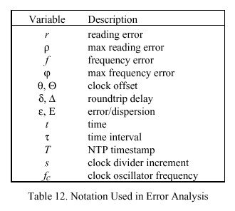
The notation w = [u,v] in the following describes the interval in which u is the lower limit and v the upper limit, inclusive. Thus, u = min (w) <= v = max (w), and for scalar a, w + a = [u + a, v + a]. Table 12 shows a summary of other notation used in the analysis. The notation <x> designates the (infinite) average of x, which is usually approximated by an exponential average, while the notation x "hat" designates an estimator for x. The lower-case Greek letters theta, delta and epsilon are used to designate measurement data for the local clock to a peer clock, while the upper-case Greek letters THETA, DELTA and EPSILON are used to designate measurement data for the local clock relative to the primary reference source at the root of the synchronization subnet. Exceptions will be noted as they arise.
Timestamp Errors
The standard second (1 s) is defined as "9,192,631,770 periods of the radiation corresponding to the transition between the two hyperfine levels of the ground state of the cesium-133 atom" [ALL74b], which implies a granularity of about 1.1x10⁻¹⁰ s. Other intervals can be determined as rational multiples of 1 s. While NTP time has an inherent resolution of about 2.3x10⁻¹⁰ s, local clocks ordinarily have resolutions much worse than this, so the inherent error in resolving NTP time relative to the 1 s can be neglected.
In this analysis the local clock is represented by a counter/divider which increments at intervals of s seconds and is driven by an oscillator which operates at frequency f sub c = n over s for some integer n. A timestamp T(t) is determined by reading the clock at an arbitrary time t (the argument t will be usually omitted for
conciseness). Strictly speaking, s is not known exactly, but can be assumed bounded from above by the maximum reading error rho. The reading error itself is represented by the random variable r bounded by the interval [-rho ,0], where rho depends on the particular clock implementation. Since the intervals between reading the same clock are almost always independent of and much larger than s, successive readings can be considered independent and identically distributed. The frequency error of the clock oscillator is represented by the random
variable f bounded by the interval [-phi ,phi ], where phi represents the maximum frequency tolerance of the oscillator throughout its service life. While f for a particular clock is a random variable with respect to the population of all clocks, for any one clock it ordinarily changes only slowly with time and can usually be assumed a constant for that clock. Thus, an NTP timestamp can be represented by the random variable T:
T = t + r + f tau ,
where t represents a clock reading, tau represents the time interval since this reading and minor approximations inherent in the measurement of tau are neglected.
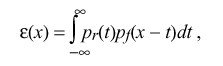
In order to assess the nature and expected magnitude of timestamp errors and the calculations based on them, it is useful to examine the characteristics of the probability density functions (pdf) p sub r (x) and p sub f (x) for r and f respectively. Assuming the clock reading and counting processes are independent, the pdf for r is uniform
over the interval [-rho ,0]. With conventional manufacturing processes and temperature variations the pdf for f can be approximated by a truncated, zero-mean Gaussian distribution with standard deviation sigma. In conventional manufacturing processes sigma is maneuvered so that the fraction of samples rejected outside the interval [-phi ,phi ] is acceptable. The pdf for the total timestamp error epsilon (x) is thus the sum of the r and f contributions, computed as
which appears as a bell-shaped curve, symmetric about -rho over 2 and bounded by the interval
![]()
Since f changes only slowly over time for any single clock,
![]()
where epsilon without argument designates the interval and epsilon (x) designates the pdf. In the following development subscripts will be used on various quantities to indicate to which entity or timestamp the quantity applies. Occasionally, epsilon will be used to designate an absolute maximum error, rather than the interval, but the distinction will be clear from context.
Measurement Errors
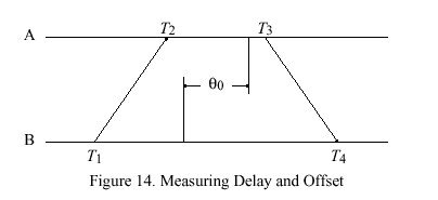
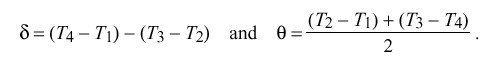
In NTP the roundtrip delay and clock offset between two peers A and B are determined by a procedure in which timestamps are exchanged via the network paths between them. The procedure involves the four most recent timestamps numbered as shown in Figure 14, where the theta sub 0 represents the true clock offset of peer B relative to peer A. The T sub 1 and T sub 4 timestamps are determined relative to the A clock, while the T sub 2 and T sub 3 timestamps are determined relative to the B clock. The measured roundtrip delay delta and clock offset theta of B relative to A are given by
The errors inherent in determining the timestamps T1, T2, T3 and T4 are, respectively,
![]()
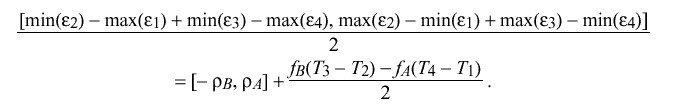
For specific peers A and B, where f sub A and f sub B can be considered constants, the interval containing the maximum error inherent in determining delta is given by

In the NTP local clock model the residual frequency errors f sub A and f sub B are minimized through the use of a type-II phase-lock loop (PLL). Under most conditions these errors will be small and can be ignored. The pdf for the remaining errors is symmetric, so that delta "hat" = <delta> is an unbiased maximum-likelihood estimator for the true roundtrip delay, independent of the particular values of rho sub A and rho sub B.
However, in order to reliably bound the errors under all conditions of component variation and operational regimes, the design of the PLL and the tolerance of its intrinsic oscillator must be controlled so that it is not possible under any circumstances for f sub A or f sub B to exceed the bounds [-phi sub A ,phi sub A ] or [-phi sub B ,phi sub B ], respectively. Setting rho = max ( rho sub A ,rho sub B ) for convenience, the absolute maximum error epsilon sub delta inherent in determining roundtrip delay delta is given by
![]()
neglecting residuals.
As in the case for delta, where f sub A and f sub B can be considered constants, the interval containing the maximum error inherent in determining theta is given by
Under most conditions the errors due to f sub A and f sub B will be small and can be ignored. If rho sub A = rho sub B = rho; that is, if both the A and B clocks have the same resolution, the pdf for the remaining errors is symmetric, so that theta "hat" = < theta > is an unbiased maximum-likelihood estimator for the true clock offset theta sub 0, independent of the particular value of rho. If rho sub A != rho sub B, < theta > is not an unbiased estimator; however, the bias error is in the order of
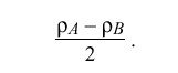
and can usually be neglected.
Again setting rho = max ( rho sub A , rho sub B ) for convenience, the absolute maximum error epsilon sub theta inherent in determining clock offset theta is given by
Network Errors
In practice, errors due to stochastic network delays usually dominate. In general, it is not possible to characterize network delays as a stationary random process, since network queues can grow and shrink in chaotic fashion and arriving customer traffic is frequently bursty. However, it is a simple exercise to calculate bounds on clock offset
errors as a function of measured delay. Let T sub 2 - T sub 1 = a and T sub 3 - T sub 4 = b. Then,
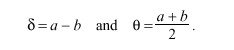
The true offset of B relative to A is called theta sub 0 in Figure 14. Let x denote the actual delay between the departure of a message from A and its arrival at B. Therefore, x + theta sub 0 = T sub 2 - T sub 1 == a . Since x must be positive in our universe, x = a - theta sub 0 >= 0, which requires theta sub 0 <= a. A similar argument requires that b <= theta sub 0, so surely b <= theta sub 0 <= a. This inequality can also be expressed
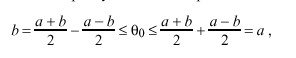
which is equivalent to
![]()
In the previous section bounds on delay and offset errors were determined. Thus, the inequality can be written
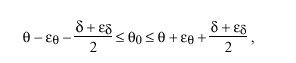
where epsilon sub theta is the maximum offset error and epsilon sub delta is the maximum delay error derived previously. The quantity
called the peer dispersion, defines the maximum error in the inequality. Thus, the correctness interval I can be defined as the interval
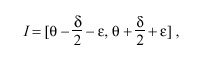
in which the clock offset C = theta is the midpoint. By construction, the true offset theta sub 0 must lie somewhere in this interval.
Inherited Errors
As described in the NTP specification, the NTP time server maintains the local clock THETA, together with the root roundtrip delay delta and root dispersion EPSILON relative to the primary reference source at the root of the synchronization subnet. The values of these variables are either included in each update message or can be derived as described in the NTP specification. In addition, the protocol exchange and clock-filter algorithm provide the clock offset THETA and roundtrip delay delta of the local clock relative to the peer clock, as well as various error accumulations as described below. The following discussion establishes how errors inherent in the time-transfer process accumulate within the subnet and contribute to the overall error budget at each server.
An NTP measurement update includes three parts: clock offset theta, roundtrip delay delta and maximum error or dispersion epsilon of the local clock relative to a peer clock. In case of a primary clock update, these values are usually all zero, although EPSILON can be tailored to reflect the specified maximum error of the primary reference source itself. In other cases THETA and delta are calculated directly from the four most recent timestamps, as described in the NTP specification. The dispersion EPSILON includes the following contributions:
| • | 1. Each time the local clock is read a reading error is incurred due to the finite granularity or precision of the implementation. This is called the measurement dispersion rho. |
| • | 2. Once an offset is determined, an error due to frequency offset or skew accumulates with time. This is called the skew dispersion phi tau, where phi represents the skew-rate constant (NTP.MAXSKEW over NTP.MAXAGE in the NTP specification) and tau is the interval since the dispersion was last updated. |
| • | 3. When a series of offsets are determined at regular intervals and accumulated in a window of samples, as in the NTP clock-filter algorithm, the (estimated) additional error due to offset sample variance is called the filter dispersion epsilon sub sigma. |
| • | 4. When a number of peers are considered for synchronization and two or more are determined to be correctly synchronized to a primary reference source, as in the NTP clock-selection algorithm, the (estimated)additional error due to offset sample variance is called the selection dispersion epsilon sub xi. |
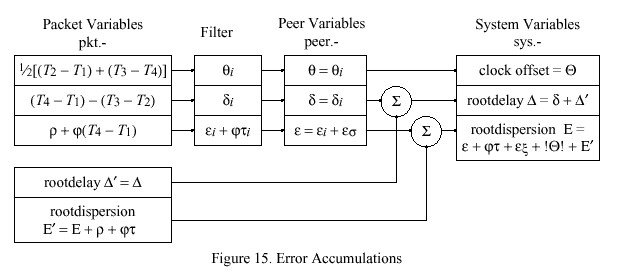
Figure 15 shows how these errors accumulate in the ordinary course of NTP processing. Received messages from a single peer are represented by the packet variables. From the four most recent timestamps T1, T2, T3 and T4 the clock offset and roundtrip delay sample for the local clock relative to the peer clock are calculated directly. Included in the message are the root roundtrip delay DELTA prime and root dispersion EPSILON prime of the peer itself; however, before sending, the peer adds the measurement dispersion rho and skew dispersion phi tau, where these quantities are determined by the peer and tau is the interval according to the peer clock since its clock was last updated.
The NTP clock-filter procedure saves the most recent samples theta sub i and delta sub i in the clock filter as described in the NTP specification. The quantities rho and phi characterize the local clock maximum reading error and frequency error, respectively. Each sample includes the dispersion epsilon sub i = rho + phi (T sub 4 - T sub 1 ), which is set upon arrival. Each time a new sample arrives all samples in the filter are updated with the skew dispersion phi tau sub i, where tau sub i is the interval since the last sample arrived, as recorded in the variable peer.update. The clock-filter algorithm determines the selected clock offset theta (peer.offset), together with the associated roundtrip delay delta (peer.delay) and filter dispersion epsilon sub sigma, which is added to the associated sample dispersion epsilon sub i to form the peer dispersion epsilon (peer.dispersion).
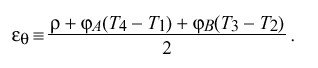
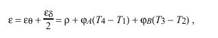
The NTP clock-selection procedure selects a single peer to become the synchronization source as described in the NTP specification. The operation of the algorithm determines the final clock offset THETA (local clock), roundtrip delay DELTA (sys.rootdelay) and dispersion EPSILON (sys.rootdispersion) relative to the root of the synchronization subnet, as shown in Figure 15. Note the inclusion of the selected peer dispersion and skew accumulation since the dispersion was last updated, as well as the select dispersion epsilon sub xi computed by the clock-select algorithm itself. Also, note that, in order to preserve overall synchronization subnet stability, the final clock offset THETA is in fact determined from the offset of the local clock relative to the peer clock, rather than the root of the subnet. Finally, note that the packet variables DELTA prime and EPSILON prime are in fact determined from the latest message received, not at the precise time the offset selected by the clock-filter algorithm was determined. Minor errors arising due to these simplifications will be ignored. Thus, the total dispersion accumulation relative to the root of the synchronization subnet is
![]()
where tau is the time since the peer variables were last updated and | THETA | is the initial absolute error in setting the local clock.
The three values of clock offset, roundtrip delay and dispersion are all additive; that is, if THETA sub i, DELTA sub i and EPSILON sub i represent the values at peer i relative to the root of the synchronization subnet, the values
![]()
represent the clock offset, roundtrip delay and dispersion of peer j at time t. The time dependence of theta sub j (t) and epsilon sub j (t) represents the local-clock correction and dispersion accumulated since the last update was received from peer i, while the term epsilon sub i represents the dispersion accumulated by peer i from the time its clock was last set until the latest update was sent to peer j. Note that, while the offset of the local clock relative to the peer clock can be determined directly, the offset relative to the root of the synchronization subnet is not directly determinable, except on a probabilistic basis and within the bounds established in this and the previous section.
The NTP synchronization subnet topology is that of a tree rooted at the primary server(s). Thus, there is an unbroken path from every time server to the primary reference source. Accuracy and stability are proportional to synchronization distance LAMBDA, defined as
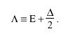
The selection algorithm favors the minimum-distance paths and thus maximizes accuracy and stability. Since THETA sub 0, DELTA sub 0 and EPSILON sub 0 are all zero, the sum of the clock offsets, roundtrip delays and dispersions of each server along the minimum-distance path from the root of the synchronization subnet to a given server i are the clock offset THETA sub i, roundtrip delay DELTA sub i and dispersion EPSILON sub i inherited by and characteristic of that server.
Correctness Principles
In order to minimize the occurrence of errors due to incorrect clocks and maximize the reliability of the service, NTP relies on multiple peers and disjoint peer paths whenever possible. In the previous development it was shown that, if the primary reference source at the root of the
synchronization subnet is in fact a correct clock, then the true offset theta sub 0 relative to that clock must be contained in the interval
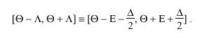
When a number of clocks are involved, it is not clear beforehand which are correct and which are not; however, as cited previously, there are a number of techniques based on clustering and filtering principles which yield a high probability of detecting and discarding incorrect clocks. Marzullo and Owicki [MAR85] devised an algorithm designed to find an appropriate interval containing the correct time given the confidence intervals of m clocks, of which no more than f are considered incorrect. The algorithm finds the smallest single intersection containing all points in at least m - f of the given confidence intervals.
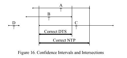
Figure 16 illustrates the operation of this algorithm with a scenario involving four clocks A, B, C and D, with the calculated time (shown by the up arrow symbol) and confidence interval shown for each. These intervals are computed as described in previous sections of this appendix. For instance, any point in the A interval may possibly represent the actual time associated with that clock. If all clocks are correct, there must exist a nonempty intersection including all four intervals; but, clearly this is not the case in this scenario. However, if it is assumed that one of the clocks is incorrect (e.g., D), it might be possible to find a nonempty intersection including all but one of the intervals. If not, it might be possible to find a nonempty intersection including all but two of the intervals and so on.
The algorithm proposed by DEC for use in the Digital Time Service [DEC89] is based on these principles. For the scenario illustrated in Figure 16, it computes the interval for m = 4 clocks, three of which turn out to be correct and one not. The low endpoint of the intersection is found as follows. A variable f is initialized with the number of presumed incorrect clocks, in this case zero, and a counter i is initialized at zero. Starting from the lowest endpoint, the algorithm increments i at each low endpoint, decrements i at each high endpoint, and stops when i >= m - f . The counter records the number of intersections and thus the number of presumed correct clocks. In the example the counter never reaches four, so f is increased by one and the procedure is repeated. This time the counter reaches three and stops at the low endpoint of the intersection marked DTS. The upper endpoint of this intersection is found using a similar procedure.
This algorithm will always find the smallest single intersection containing points in at least one of the original m - f confidence intervals as long as the number of incorrect clocks is less than half the total f < m over 2. However, some points in the intersection may not be contained in all m - f of the original intervals; moreover, some or all of the calculated times (such as for C in Figure 16) may lie outside the intersection. In the NTP clock-selection procedure the above algorithm is modified so as to include at least m -f of the calculated times. In the modified algorithm a counter c is initialized at zero. When starting from either endpoint, c is incremented at each calculated time; however, neither f nor c are reset between finding the low and high endpoints of the intersection. If after both endpoints have been found c > f, f is increased by one and the entire procedure is repeated. The revised algorithm finds the smallest intersection of m - f intervals containing at least m - f calculated times. As shown in Figure 16, the modified algorithm produces the intersection marked NTP and including the calculated time for C.
In the NTP clock-selection procedure the peers represented by the clocks in the final intersection, called the survivors, are placed on a candidate list. In the remaining steps of the procedure one or more survivors may be discarded from the list as outlyers. Finally, the clock-combining algorithm described in Appendix F provides a weighted average of the remaining survivors based on synchronization distance. The resulting estimates represent a synthetic peer with offset between the maximum and minimum offsets of the remaining survivors. This defines the clock offset THETA, total roundtrip total delay delta and total dispersion EPSILON which the local clock inherits. In principle, these values could be included in the time interface provided by the operating system to the user, so that the user could evaluate the quality of indications directly.